CAD Process
The measurements and modeling process.

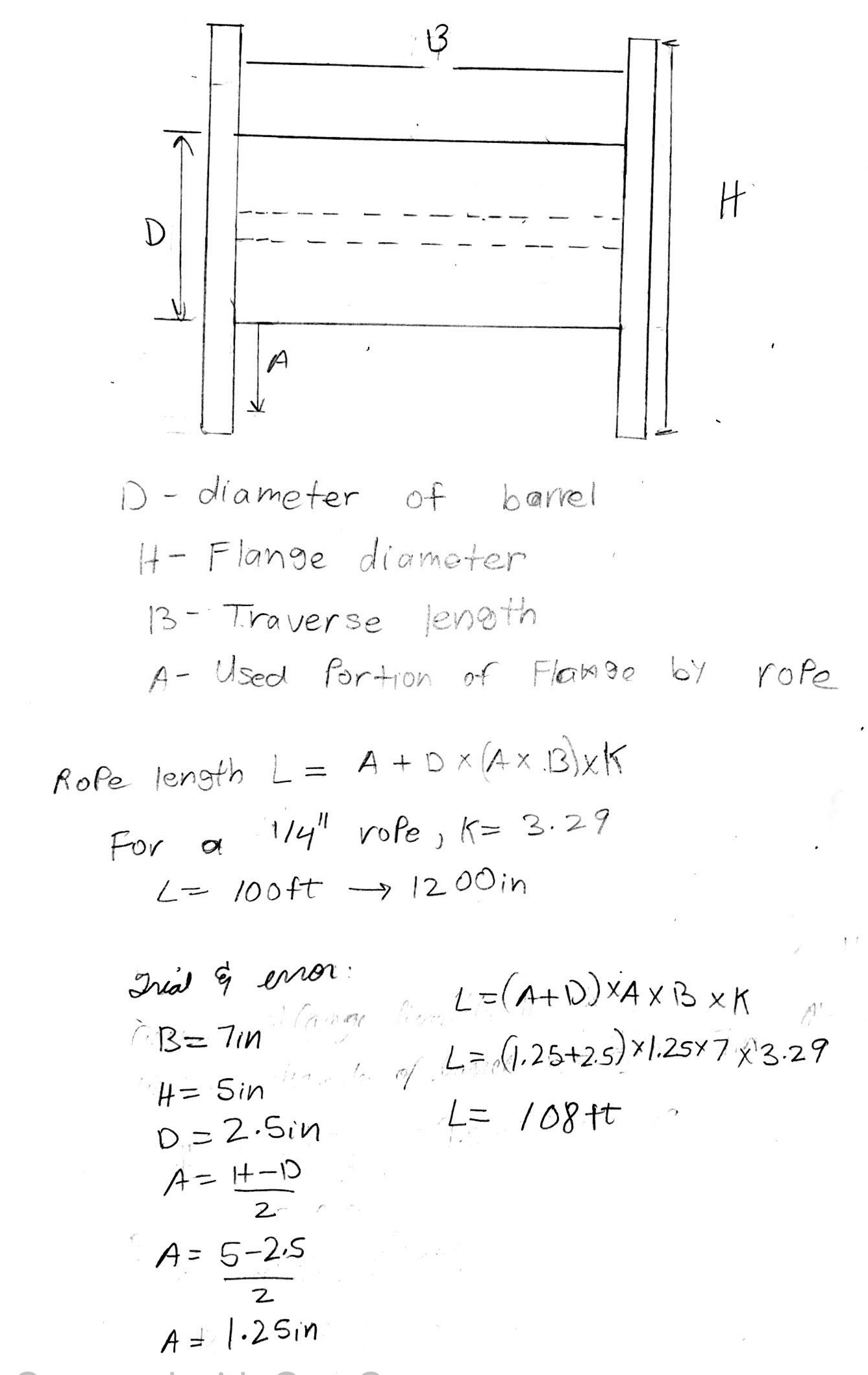
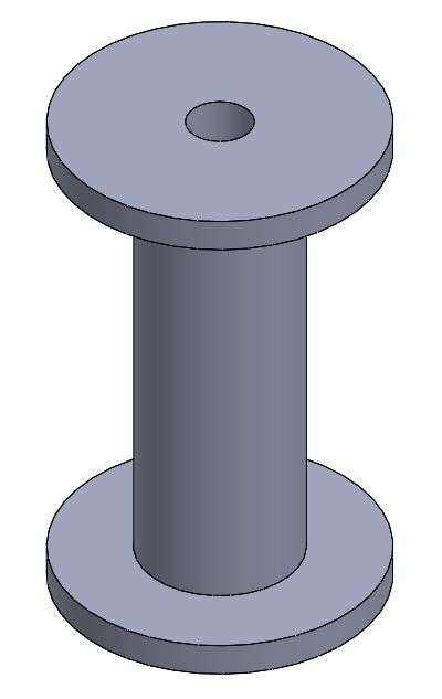
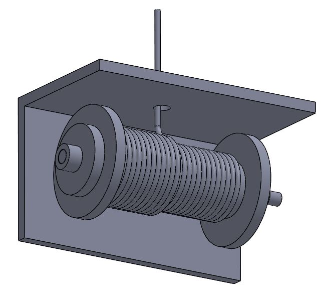
This was our spool that could hold 100 ft of 1/4 inch rope.
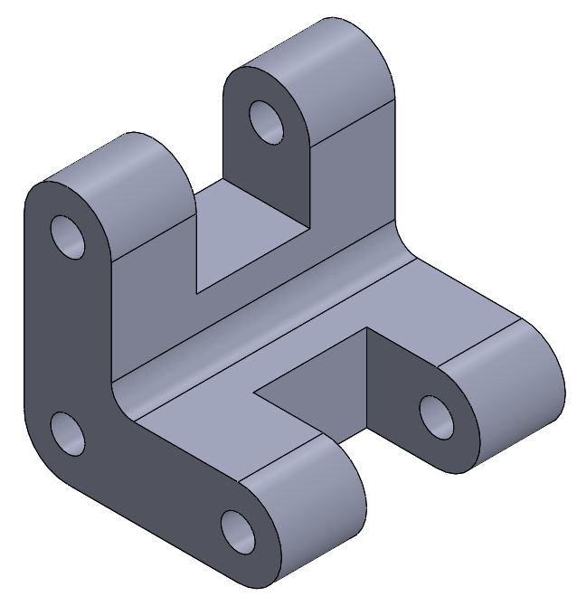
In order to hold the spool, a rod will be passed through and fixed on either end by the braking system case.
To hold the spool in the center, a part such as a flange will be used to keep the spool in place.
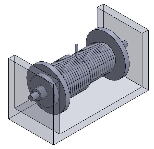
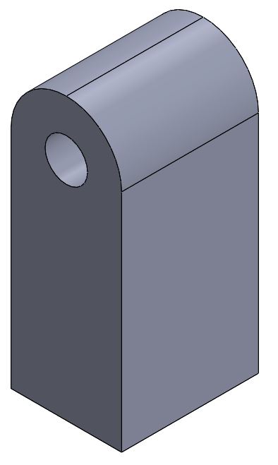
In order to make sure the rope spools out from the same location, a rope guide was created.
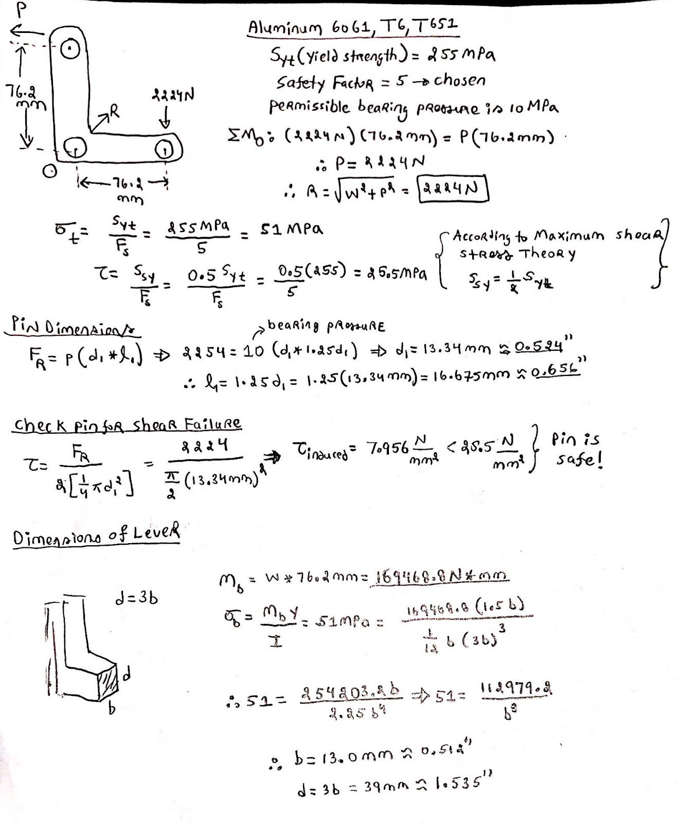
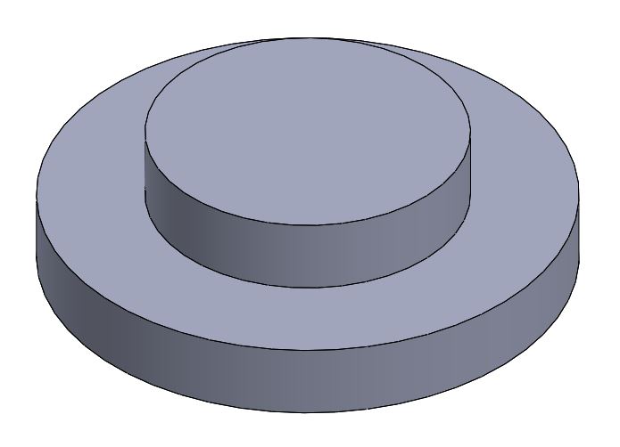
This was our original crank design, based on the calculations.
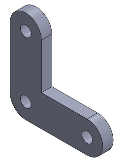
After looking at the crank in the context of the whole system, we decided to increase the thickness to be able to properly hold the force of the spring.
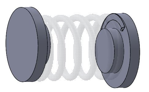
Additionally, we also modified the design to symmetrically hold the levers and smoothly rotate by the weight of the person.
The arms were created based on the space available after the crank and springs were positioned.
With the crank,
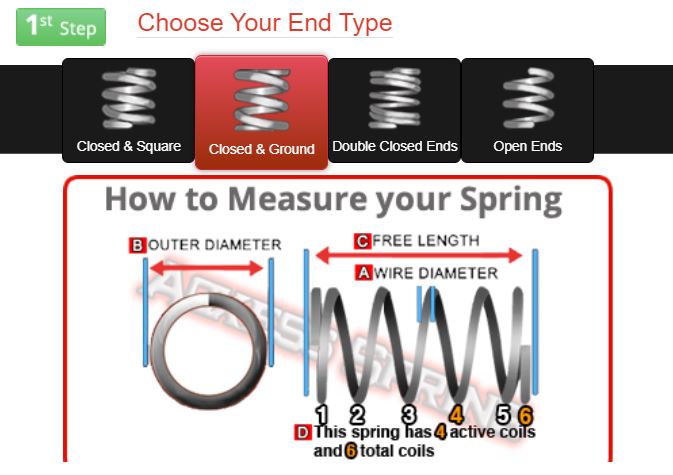
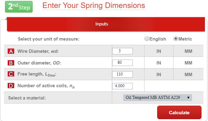


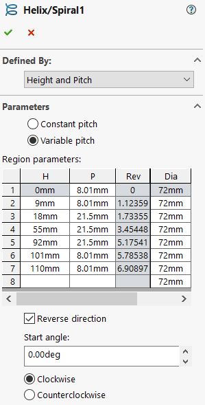
In order to create free-length closed and ground springs, which were necessary in order to fit the springs in the spring cups, a variable pitch had to be manually determined and inputted into SolidWorks.The solid spring could be made using a constant pitch.
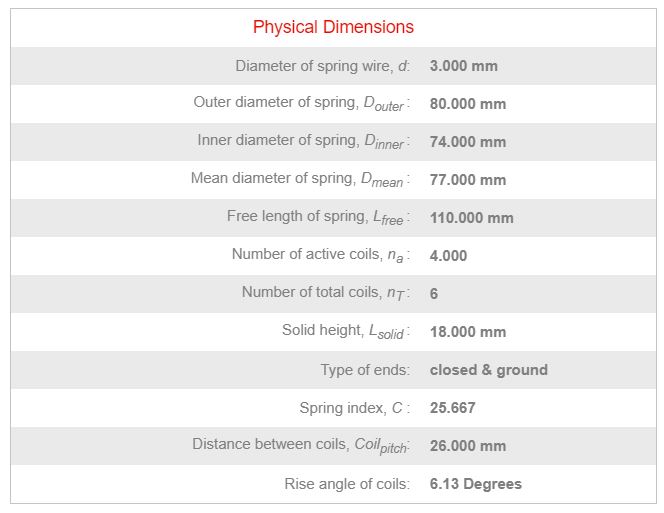
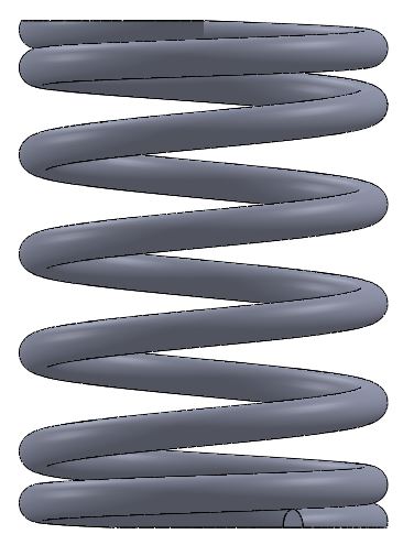
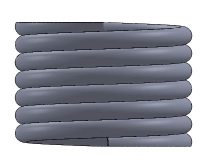
The result for the free length and solid spring is below:
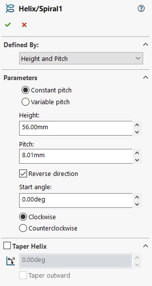
These inputs, and cuts on the top and bottom to grind the springs, give the spring shape:
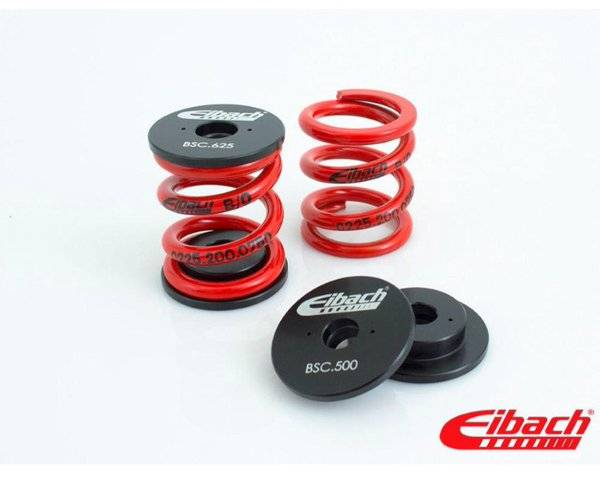
Using these dimensions, a spring cup was created to hold the springs in place.