Design Process
The designing process.
We narrowed down our concept to two scenarios:
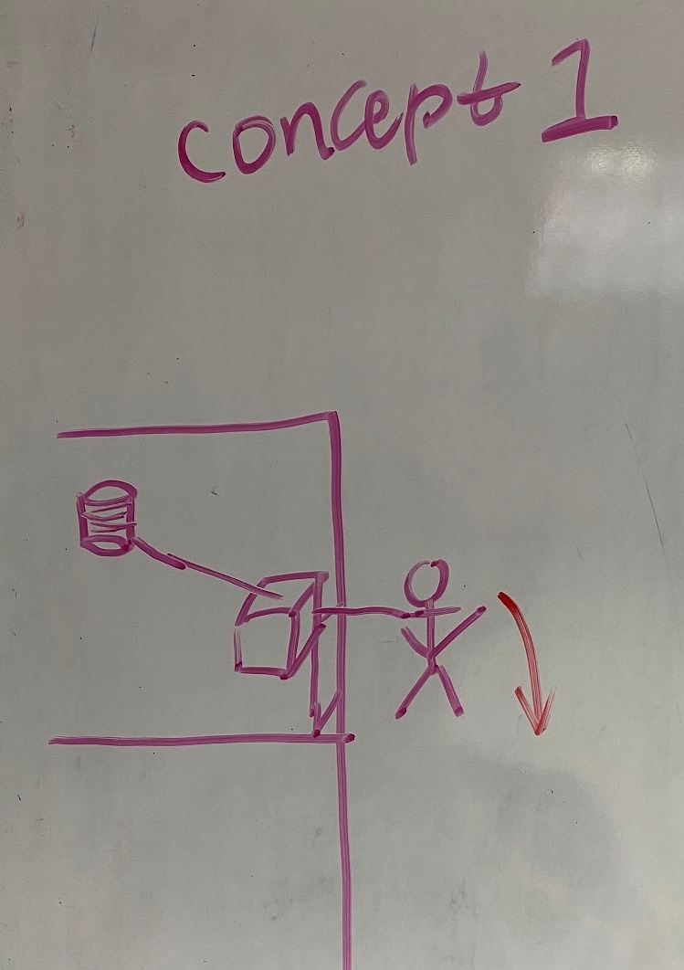
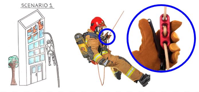
1) The rope is spooled out of a pulley and the user descends with the rope.
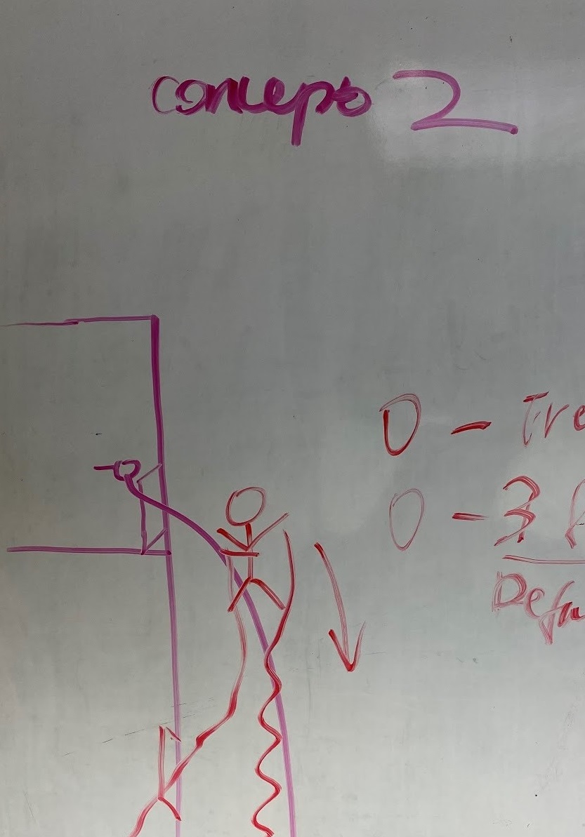
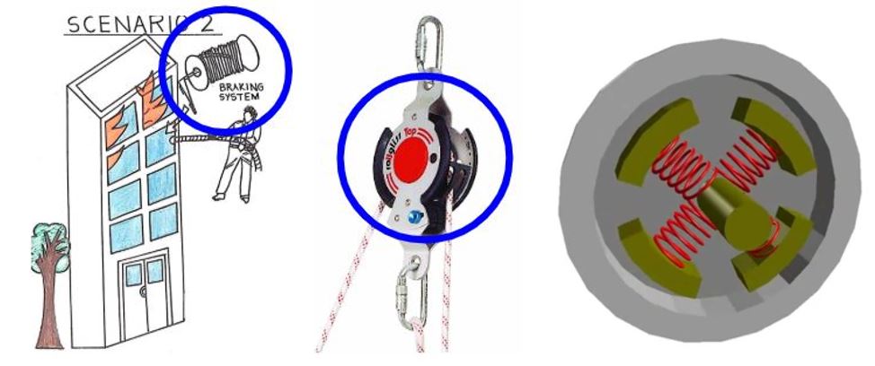
2) The user throws the rope down the window, and then descends down the rope.
We looked at the two scenarios and found a possible braking system for each case.
The first scenario involved a pre-tossed rope, and firefighters use a manual braking system such as an F4 Escape System to descend.
The second scenario involves a rope being spooled out, and one way of using the spin of the pulley is by using a centrifugal braking mecahnism. However, we were inspired by the braking system of a fishing rod and do not know how big it will have to be to brake a 500 lb weight, versus a fish.
We ultimately chose to go with the pre-tossed rope scenario.
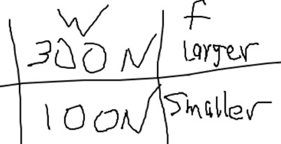
We needed a system that applied more friction (f) for a larger weight, and less friction for a smaller weight.
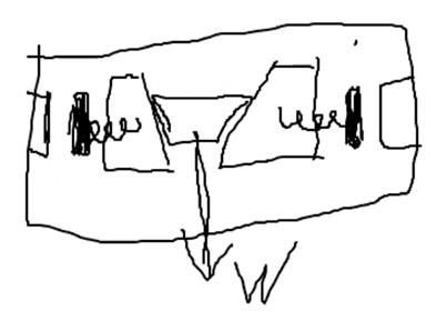
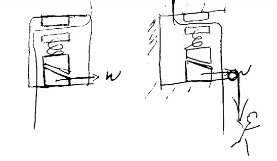
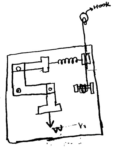
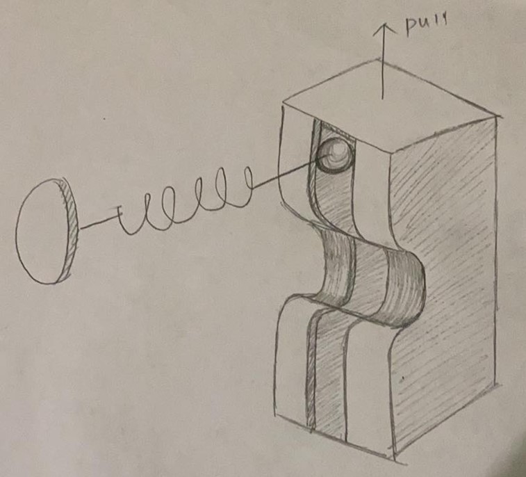
We thought of a system that uses a wedge that pulls outwards to adjust the amount of friction being applied on the rope.
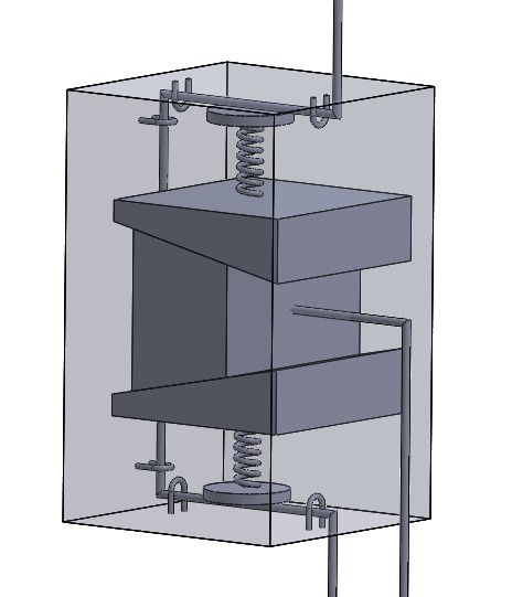
We chose to orient the wedge system vertically, since our rope was going down vertically. An initial CAD model was created to better understand details to be figured out.
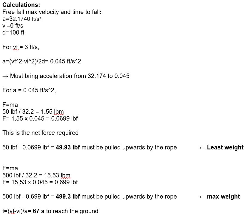
We calculated the amount of force required to land the user at 3 ft/s, taking into account gravitational acceleration.
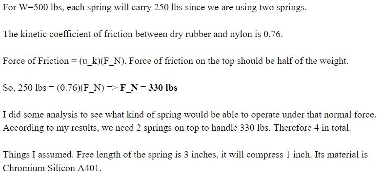
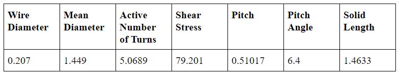
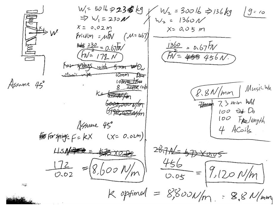
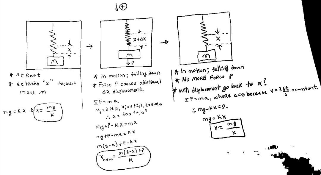
We realized that we can use terminal velocity to bring the acceleration to 0 by applying a frictional force equivalent to the weight of the user. The specifications of the springs were then roughly estimated.
We concluded that we should be able to use a spring with specifications that lie in between the requirements for braking a 50 lb weight and a 500 lb weight.
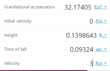
The time it takes for the system to reach 3 ft/s was determined using this calculator.
Therefore, the brake has to kick in when 0.09 seconds has passed from when the user initially falls in order to maintain a terminal velocity of 3 ft/s.
However, this time seems too specific and short, and does not allow room for error.
We noticed a major flaw in our design, that the user's weight will not pull the wedge out if the whole system is in motion, because the frame of reference is also in motion and relative velocity is therefore 0.
The whole system therefore has to be somehow fixed initially.
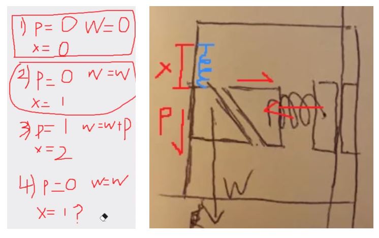
We decided to change the orientation and have the system initially be at a hard brake.
However, this required an additional force to be applied for a split second to release the hard brake after the user's weight has pulled out the wedge, since the system has to move up to 3 ft/s, and then kept at terminal velocity by having a frictional force equivalent to the user weight. This proved to be difficult to achieve.
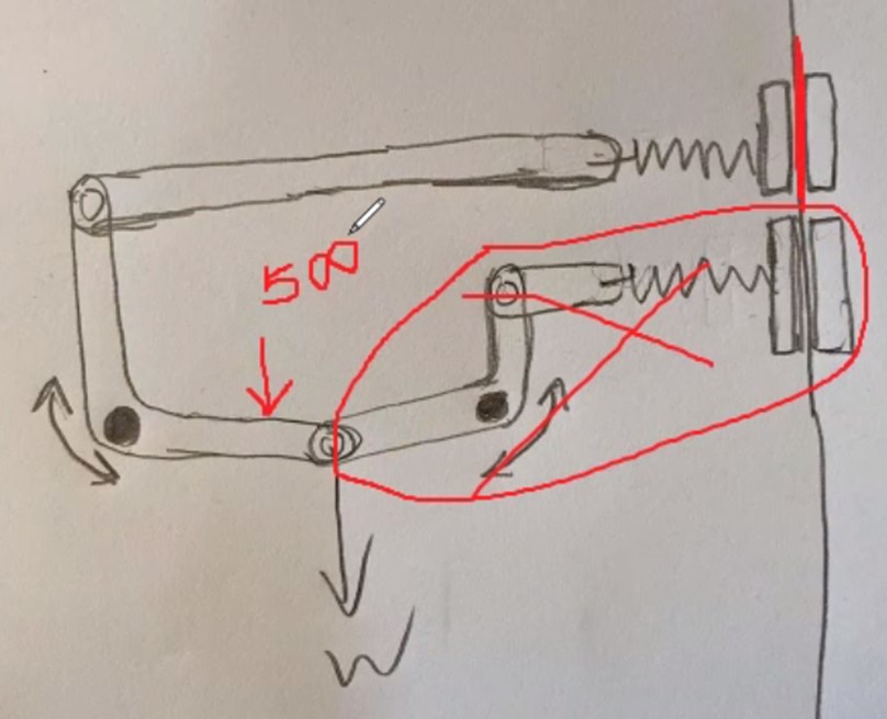
Additionally, this system decreases friction with an increasing weight and therefore did not work out.
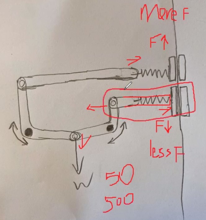
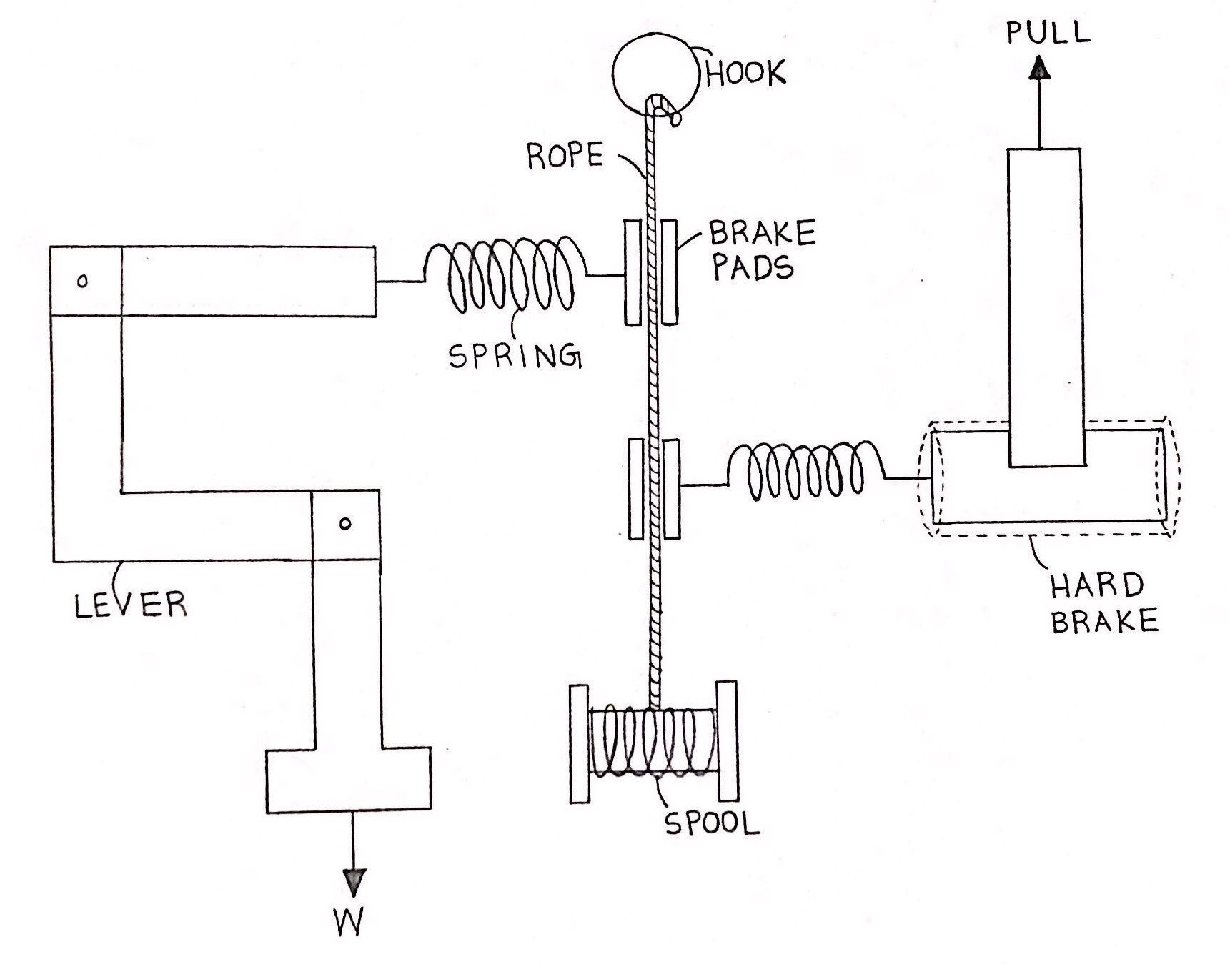
We then came up with a new design that involves a crank that pushes a brakepad when the user's weight pulls an arm down. This removed the difficulties determining the wedge angle, friction between the wedge and brake pad block, and more.
We tried to design a hard brake system using springs. However, this complicated the system and also distributed the weight among initially two springs, and then transferred the weight to one spring only, causing a difference in force with the release of the hard brake.
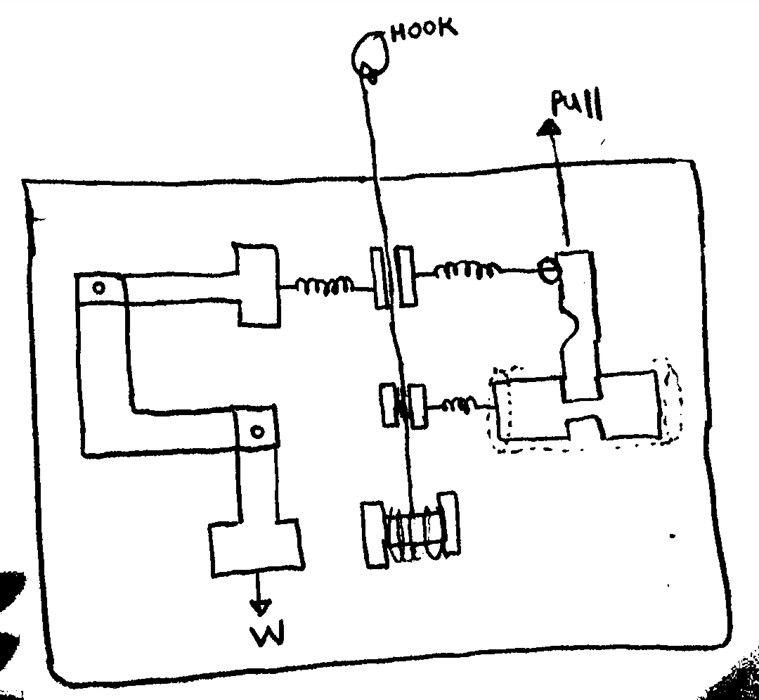
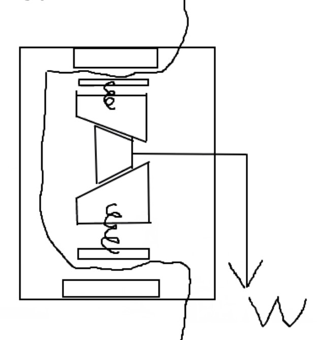
We created a hard brake that is initially supplied by a fully compressed spring, and is released when a stopper keeping the spring compressed is pulled out. At the same time, a spring at the top opposite to the weight-dependent spring is released for a split second to provide the initial momentum.
We ultimately decided to remove the top right spring opposing the weight-dependent spring completely as it complicated our system. The system will instead move for a split second to reach 3 ft/s by having the brake pads initially go through a section of rope of a lower coefficient of friction.
This was our final concept prior to modeling.
We ended up reverting to the pulley system where the user goes down with the rope.
As the system was modeled, details were added as can be read here.
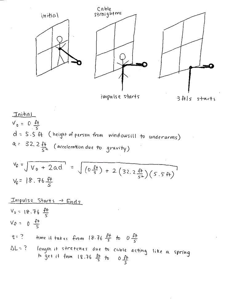
We first had to determine the load the clasp will have to withstand. Although the maximum user weight we intend the system for is 500 lbs, there exists an initial impact that is greater than that load.
To calculate this impact load, we initially imagined the user to be standing on top of the window ledge, and free falls down until the user drops down to the side of the window ledge. At this point, the rope is taut and the user will begin descending at a constant rate set by us.
We eventually decided that the user will not choose to stand on the ledge and allow themselves to free fall from a such a height, and will instead choose to slowly go off of the window ledge.
After numerous calculations, we concluded that it is very difficult to figure out the impact load. Therefore, we used a rule of thumb of the impact load being two times the static load.
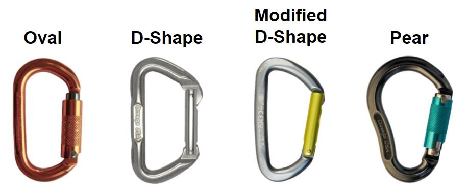
We chose to use a carabiner because it is common, simple to use, and has a history of being safe to use for high-risk activities such as rock climbing, hang gliding, and bungee jumping.
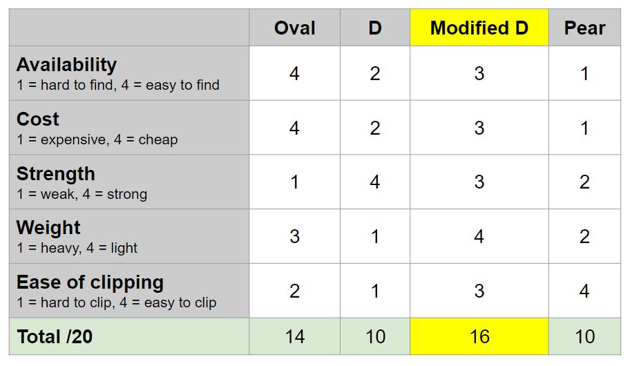
We used an evaluation matrix to conclude that the best carabiner shape to use is a modified D-shape.
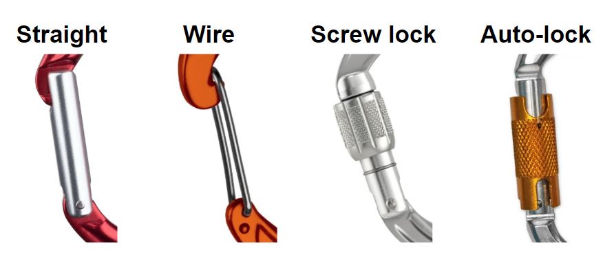
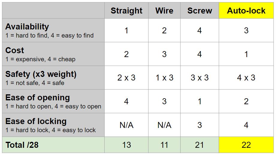
We created a similar matrix for the carabiner gate type. We chose an auto-lock gate mainly based on its secureness and relative ease of opening and closing.
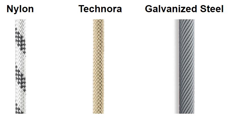
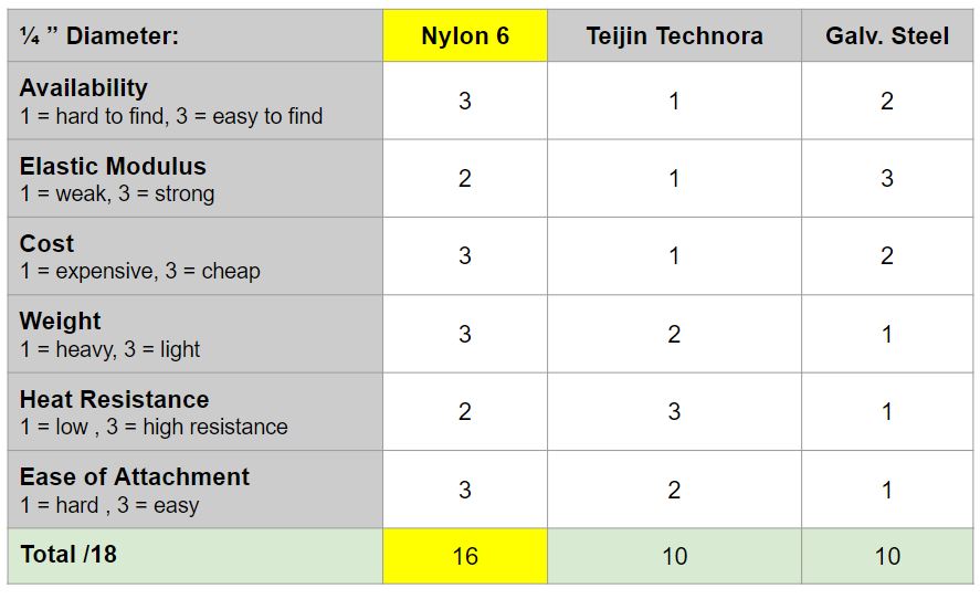
We had to choose a rope material that was flame resistant and can withstand a dynamic load of up to 1000 lbf.
We evaluated three different commonly used for escape rope materials using a matrix.
We found nylon to be the best material for our purpose.
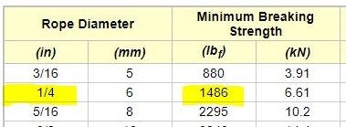
We looked at the data provided by Engineering ToolBox and found that for a 1000 lbf (dynamic) force, a 1/4 inch diameter rope will suffice.
While researching, we found a National Fire Protection Association (NFPA) standard on Life Safety Rope and Equipment for Emergency Services, which is what we are trying to design.
However, being approved for these standards will drive up our product cost and may not be necessary, and therefore we chose to loosely follow the guidelines where we see fit.
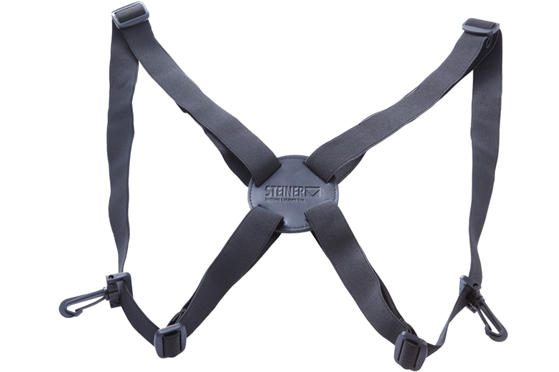
We chose to use a shoulder harness because it is easy for the user to put on.
We will need to make sure that the material is fire proof.